In the world of civil engineering and large-scale earthworks, precision is the difference between a profitable project and a financial disaster. Whether you’re leveling a site for a new housing development or carving out a path for a highway, it doesn’t matter. You always need a clear strategy for moving earth. It’s where a cut-and-fill analysis becomes indispensable. This is the process of calculating exactly:
- How much soil do you need to remove from high points
- How much do you need to add to low areas to create a perfectly level or graded surface
Accurate cut fill analysis does more than move dirt. It saves money. For example, your estimates are off. Then you might end up paying extra for trucks to haul away the soil. Or, worse, you will pay to bring in expensive fill material from an outside source. By balancing the site correctly, you keep your costs low and your timeline on track. Proper site grading also ensures the foundation of your project is stable, and water flows exactly where it should.
To achieve these precise results, pros rely on a mix of detailed field measurements, visual aids such as a cut-and-fill diagram, and advanced software. Our guide will walk you through the core concepts and best practices. We will ensure your earthwork estimates are as accurate as possible.
What Is Cut-and-Fill? Core Concepts Explained
Cut-and-fill construction is a technique for reshaping land by moving material within the site rather than importing or exporting it. “Cut” is what you remove from areas where the ground sits higher than your target grade. “Fill” is what you place in areas where it’s too low. The goal is a balanced site – the volume you cut roughly equals the volume you need to fill.
This matters in several types of work:
- Road construction. A highway through hilly terrain can’t climb and descend with the natural topography. The hillsides are cut down, and the valleys are filled in to maintain a consistent grade.
- Building sites. A flat, compacted pad is needed before a foundation goes in. That often means cutting some areas and filling others to achieve a level surface.
- Landscaping and drainage. How water moves across a site depends on the ground’s shape. Cut-and-fill construction controls at the design stage.
The long-term consequences of doing this badly show up later. Fill material that wasn’t properly compacted settles over time – cracked slabs, failing road surfaces, uneven floors. Grading that doesn’t account for drainage can cause flooding. These aren’t construction problems in the traditional sense; they’re earthwork issues that arose in the planning phase.
Cut-and-Fill Method: Step-by-Step Process
The cut-and-fill method starts before any equipment arrives. It starts with accurate survey data.
Surveyors map the existing ground elevation across the site using GPS, robotic total stations, or drone-based photogrammetry. This produces the “existing grade” – a precise picture of what the site looks like now. Engineers then compare it to the “proposed grade” – what the site will look like when work is done. The difference between the two, calculated at every point across the site, is the cut-and-fill.
The technical steps that follow:
- Topographic mapping. A detailed model of existing surface conditions. The accuracy of everything downstream depends on the quality of this data.
- Volume calculation. Converting the grade differences into cubic yards or cubic meters of material to be moved. This is where math lives.
- Slope design. Cut slopes that are too steep fail. Fill slopes that aren’t stable enough under load, also fail. Both need to be designed within safe limits.
- Compaction planning. This is where many estimates go wrong. Soil doesn’t behave the same way when loose as when compacted. Clay shrinks significantly when compressed. Rock expands when blasted. These “shrink and swell” factors have to be calculated and built into the volume estimates, or the numbers will be off.
Material selection for fill also matters. You can’t use any excavated dirt as structural fill. Organic material – roots, topsoil, debris – rots underground, creating voids. Fill material must be tested and approved before it is placed under a structure.
Using Cut-and-Fill Diagrams for Accurate Planning
Numbers tell you how much. A cut-and-fill diagram tells you where.
These diagrams are how the calculations get communicated to the people actually operating the machinery. A contractor reading a spreadsheet of volumes can’t tell a dozer operator where to push dirt. A cut-and-fill diagram can.
Several formats are used depending on the project:
- Cross-sections. A side view showing the existing ground line against the proposed grade. The space between the two lines represents cut or fill at that location. These are standard on-road and grading projects.
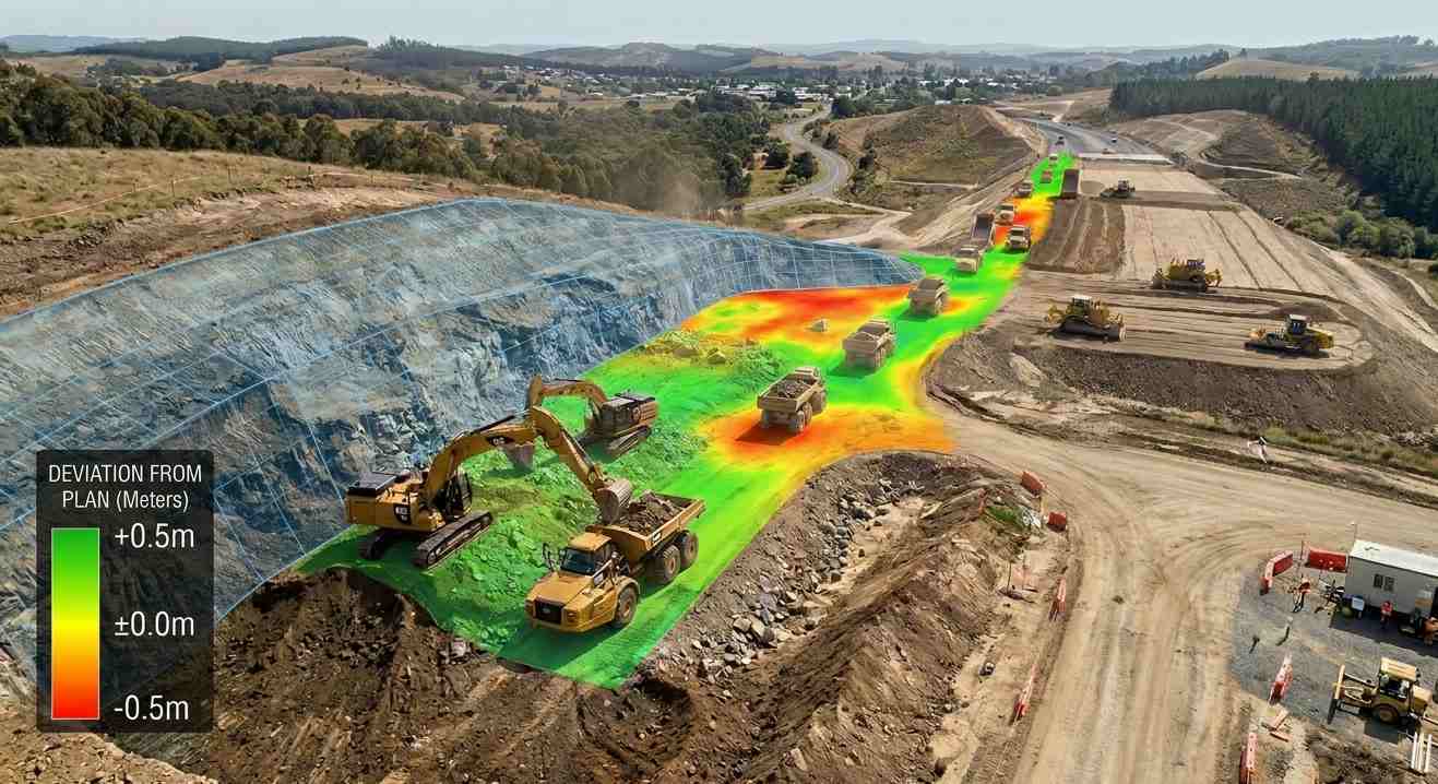
- 3D models. Color-coded renderings – typically red for cut areas, blue for fill – that show the entire site at once. Useful for project managers to track progress and identify areas that are behind schedule.
- Contour overlays. Maps that show elevation change through contour lines. Useful for understanding drainage patterns and slope steepness across large areas.
A clear cut-and-fill diagram reduces field mistakes. A crew that can see exactly how deep to excavate at a specific grid coordinate doesn’t have to guess. Progress tracking also becomes straightforward – if a section shows as complete on the diagram, but there’s still a dirt pile sitting there, the gap is immediately visible.
Tools and Software for Cut-and-Fill Analysis
Manual volume calculations by hand are still used for simple estimates, but they don’t scale. Modern cut-and-fill analysis runs on software that processes detailed terrain data and returns accurate volumes in seconds.
The standard platforms – Civil 3D, AutoCAD, various GIS-based tools – can take topographic data from a drone survey or robotic total station and build a 3D surface model. The engineer defines the proposed grade, and the software calculates the volume difference at every point. Change the finished floor elevation by a foot, and the software recalculates the whole site instantly.
The practical advantages:
- Speed. What previously took days of drafting and calculation takes minutes.
- Scenario testing. Adjusting the proposed grade to find the combination that minimizes import and export is straightforward. A small change in pad elevation can shift a project from needing to truck in fill to being self-balancing.
- Data integration. Drone photogrammetry and LiDAR outputs feed directly into these platforms. A site flown in the morning can have updated volume calculations by afternoon.
- Mass haul analysis. Beyond calculating volumes, the software can plan the most efficient movement of material across the site – which areas feed which, and what route the equipment should take. This reduces fuel costs and equipment hours.
The quality of the output is only as good as the quality of the input data. If the topographic survey is sparse or outdated, the model will be too. High-density survey data – from drone photogrammetry or laser scanning – produces much better models than a few dozen manual stakes.
Common Mistakes in Cut-and-Fill Analysis and How to Avoid Them
The same errors keep appearing on projects that go over budget or run into grading issues.
- Outdated survey data. Sites change. Erosion moves soil. Neighboring construction affects grades. Unauthorized dumping happens. If the existing conditions model is based on data that’s six months old, it may not reflect what’s actually there. Survey data should be current – ideally collected specifically for the project.
- Ignoring the shrink and swell. This is the most common source of volume calculation errors. Engineers who apply a standard factor rather than soil-specific testing end up with estimates that are noticeably off. Clay and organic soils behave very differently from sandy material. Test the soil on your specific site.
- Not separating topsoil from structural fill. Topsoil and organic material that gets stripped from the surface can’t be used as fill under structures or pavement. If the volume calculations treat all excavated material as usable fill, the estimates will show a balanced site when there’s actually a deficit.
- Skipping field verification. Software models look precise on screen. But a number that looks right in a model can be wrong because of a buried utility, an undocumented fill area, or localized soil conditions the survey didn’t capture. Walking the site and cross-referencing the model against what you can actually see catches these problems before they become construction problems.
- Not accounting for compaction. Loose fill placed at the target grade will compact over time under load. The final grade ends up lower than designed. Compaction specs need to be enforced during placement, and the design should account for expected settlement.
Best Practices for Getting Accurate Cut-and-Fill Analysis
A few practices that separate reliable cut-and-fill estimates from those that cause problems later.
- Start with dense survey data. The more data points you have, the more accurate the model. Drone photogrammetry and LiDAR capture millions of points across a site in the time it takes a ground crew to collect hundreds. The investment in better data at the start pays off in fewer surprises during construction.
- Run multiple design scenarios. Before settling on a proposed grade, test alternatives. Moving a pad elevation slightly, adjusting a road profile, changing a slope ratio – small changes can significantly affect the balance between cuе-and-fill volumes. The scenario that minimizes trucking is almost always worth finding.
- Combine software with field experience. Software calculates. It doesn’t know that a drainage ditch is likely to clog, or that a fill slope faces a direction that gets saturated in wet seasons. An experienced engineer reviewing the model catches the things the software doesn’t flag.
- Monitor during construction. Actual soil conditions rarely match the design exactly. A section of material that was expected to be sandy turns out to be clay. Rock shows up shallower than expected. Weekly checks – comparing actual progress and field conditions against the cut fill analysis – allow the plan to be adjusted before the discrepancy becomes a problem.
- Track real volumes against estimated volumes. Keep a running comparison as material is moved. If the actual cut volumes are consistently lower than estimated, the model was off somewhere. Finding that early means you can adjust procurement and hauling plans before you’re short of fill at the end of the project.
Cypress Engineering provides site grading design, topographic surveying, and cut-and-fill construction analysis for civil and development projects. Get in touch to discuss your project.